Poe Camera Not Powering on Troubleshooting
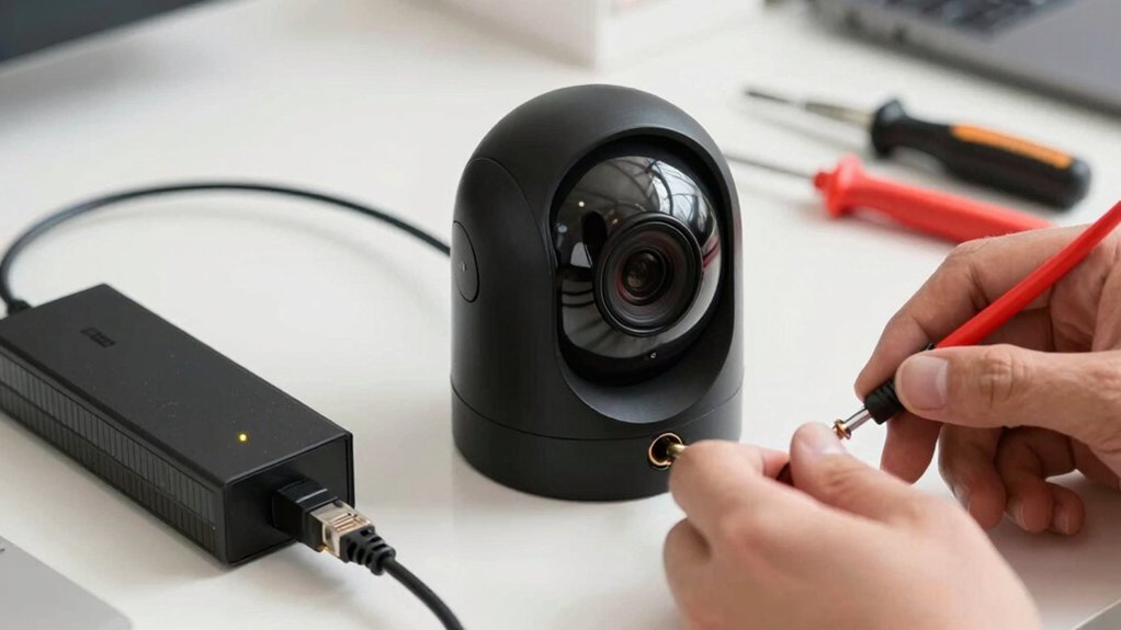
Start by checking the Ethernet plug, cable and PoE port LEDs. If a port’s power LED is off, swap to a known-good port or cable to isolate cable, port, or camera faults.
Verify the NVR/switch PoE status and total budget. Confirm active vs passive PoE and Alt A/B wiring. Measure ~48 V on powered pairs. Try a known-good camera or external DC adapter to isolate the PD.
Continue for step-by-step tests, measurements, and escalation paths.
Poe Camera Not Powering on Troubleshooting: Start by checking the Ethernet plug , cable and PoE port LEDs. If a port’s power LED is off, swap to a known-good port or cable to isolate cable, port, or camera faults. Verify the NVR/switch PoE status and total budget.
Quick Overview
- Check physical connections: Confirm RJ45 is fully seated, the cable is undamaged, and the wiring is correct (Alt A/Alt B) between the camera and NVR/switch.
- Verify PoE port LEDs and move the camera to a known-good PoE port; alternatively, use a known-good cable to isolate port versus cable faults.
- Confirm PoE compatibility: Ensure the camera’s PoE mode (active 802.3af/at or passive) and voltage match the NVR/switch or injector.
- Measure PoE voltage (~47–48 V) at the port and watch for transient drops during camera boot to detect unstable delivery.
- Test with a known-good camera or external DC adapter. If replacements power, escalate repair or replace the faulty camera or PSE.
Quick Answer: First Fixes for a PoE Camera That Won’t Power On
Having trouble getting a PoE camera to power on? Start by isolating variables: confirm the NVR/PoE switch registers PoE activity on the camera’s port. If its PoE light is off, move the cable to a different port or swap in a known-good Ethernet cable.
Verify the camera’s link to the NVR and that cable length and category meet PoE specifications to avoid voltage drop. Test with a known-good camera or another PoE device on the same port to determine whether the fault is the camera or the port/power budget.
Check the switch’s total PoE budget and temporarily unplug other cameras to rule out budget exhaustion. If the camera still won’t power, try its DC adapter (when available) to isolate a failed PoE module.
Keep this focused: don’t drift into an unrelated topic or random discussion about non-technical issues. Treat each step as a discrete diagnostic to narrow the fault quickly.
Inspect Ports, Cables, and LEDs (Physical Connection Checks)
Where do you start when a PoE camera shows no power? Begin by inspecting ports, LEDs, cables systematically. Check the NVR PoE port LEDs: if a port’s power light is off, swap the camera to a known-good port or use a different cable to rule out a faulty port.
Visually inspect cables for frays, crimps, bent pins, or loose RJ45 plugs; replace any suspect cable. Verify the camera’s Ethernet plug is fully seated, and the cable runs without sharp bends or kinks that can damage pairs.
Compare the camera-side LEDs (if present) with the NVR port LEDs to confirm power negotiation and link/activity. If both LEDs indicate no link, use a test cable and a known-good camera to isolate whether the issue is the camera, cable, or port.
Only after you isolate the physical layer should you proceed to power provisioning, firmware, or NVR configuration checks.
Check NVR/Switch PoE Status and Calculate Power Budget
Why isn’t the camera drawing power even though the cable and port look fine? Check the PoE lights and port status on the NVR or switch first: LEDs indicate whether a port is delivering power or is administratively down. Move the camera to a known-good port and use a verified cable to isolate a bad port or cord. Log each port status change so you can correlate failures.
Calculate the device power budget: sum the wattage requirements of all connected cameras and compare to the NVR/switch total PoE budget. If the aggregate exceeds available power, temporarily unplug other cameras to confirm whether the device will power on under reduced load.
Measure voltage at the PoE pins on failing ports to detect negotiation or delivery issues: active PoE should show ~48 V on power pairs. If port status shows power but voltage is absent, suspect hardware negotiation faults or a defective port.
Confirm PoE Compatibility: Active vs. Passive, Alt A/B, and 4-Pair
After you’ve ruled out port faults and power budget limits, verify that the camera and PSE actually speak the same PoE “language”: Active PoE relies on PSE/PD negotiation and follows standards (802.3af/at/bt). Passive PoE supplies a fixed voltage without negotiation and can damage or simply not power incompatible devices. You should perform compatibility verification: Confirm whether the camera expects 802.3 negotiation or a passive feed. Ensure the switch or injector matches that requirement.
Check Alt A vs. Alt B vs. 4-pair delivery modes and vendor docs to avoid mixed-mode failures. Remember: Improper mode prevents reliable power negotiation and causes no power or unstable operation.
- Validate PSE type: active (802.3) vs. passive fixed-voltage
- Confirm camera PD wiring: Alt A (data pairs) or Alt B (spare pairs)
- Check support for 4-pair (PoE++/bt) if the camera needs higher wattage
- Cross-reference vendor compatibility recommendations
- Avoid using passive supplies on devices expecting active negotiation
Test With a Known-Good Cable, Port, or Camera to Isolate Faults
Want to isolate whether the fault is the cable, port, or camera? Use controlled swaps and document outcomes systematically. Begin by replacing the suspect Ethernet cable with a known-good cable. If power/video returns, cable failure is confirmed.
If not, move the camera to a different, verified PoE port. Still dead? Place a known-good camera on the original port and cable. If the replacement camera powers, the original camera is faulty. If your camera supports external power, test with a known-good DC adapter to exclude PoE delivery. Record each step and result to avoid chasing an irrelevant topic or an unrelated concept.
| Test step | Expected diagnostic outcome |
|---|---|
| Swap to known-good cable | Restores service → cable fault |
| Move to known-good port | Restores → port fault |
| Swap in known-good camera | Restores → original camera fault |
| Use external DC adapter | Restores → PoE delivery issue |
| Document results | Identifies responsible component |
Measure PoE Voltage and Check for Shorts or Intermittent Drops
Now that you’ve isolated cable, port, and camera faults, measure PoE voltage on each active port to confirm power integrity. Use a multimeter or scope to verify ~+48 V on power pins; acceptable voltage is ~47–48 V. Monitor for transient deviations. Voltage stability and short diagnosis focus your troubleshooting steps.
Measure steady-state voltage at the RJ45 power pins and at the camera’s PoE input. Watch for intermittent drops when the camera attempts to boot; log with a scope or data-logger. Probe DC rails and across PoE board components to detect shorts to ground.
Swap to a known-good injector or switch port to compare voltage stability and isolate the fault domain. If a short is suspected, remove the PoE controller IC or suspected components temporarily to see if voltage normalizes.
These actions distinguish between delivery-path faults and internal PoE-module failures: failing controller, diodes, MOSFETs. This enables targeted repair or replacement.
Workaround: Power With a DC Adapter and Test the Camera’s PoE Module
Curious whether the camera itself is at fault or the PoE delivery, power the unit directly with its rated DC adapter and observe behavior during boot. Use a controlled DC adapter that matches the camera’s specified voltage and amperage (for example, 12V DC and the rated current). Document the adapter model and output voltage before connecting.
This power test isolates the camera from the PoE feed and lets you determine if the internal PoE module or the external PoE supply is failing. If the camera initializes, logs, or streams normally on DC power, the PoE input circuit or the feed path is the likely cause; shift troubleshooting to switch ports, injectors, and cable continuity.
If the camera still won’t boot on correct DC power, suspect an internal fault and record the adapter reference for warranty or replacement. Keep measurements and observations concise: boot indicators, LEDs, and serial output. This way, you can reproduce the condition and request the appropriate repair or replacement.
Common Installer Mistakes and Cable Best Practices to Prevent Failures
How do you avoid common installer errors that turn a reliable PoE camera into a troubleshooting headache? You reduce setup risks and eliminate installation mistakes by enforcing cable and port discipline from the start. Use certified Cat5e/Cat6 cables, keep runs under 100 meters, and replace any damaged RJ45s to prevent voltage drop and intermittent power. Verify PoE standards and switch budgets to avoid under- or over-powering cameras.
- Use certified Cat5e/Cat6; avoid runs >100 m to prevent voltage drop and intermittent failures.
- Label and verify each camera’s PoE port to prevent mislabelling and mapping errors.
- Don’t mix PoE standards (802.3af vs 802.3at) on the same port; match device and switch capabilities.
- Inspect and replace bent/missing RJ45 pins and damaged jacks; faulty contacts kill power and data.
- Distribute camera loads and calculate switch PoE budget; keep total consumption within rated capacity.
Follow these practices to minimize field failures and speed troubleshooting.
When to Escalate: Contact Support, Replace PoE Switch/Injector, or Repair Hardware
When should you escalate versus swap hardware or attempt a repair? Use clear escalation criteria: if multiple cameras lose power while NVR PoE indicators and cables test good, escalate to vendor support. This suggests a PoE controller or budget-level issue beyond basic wiring.
Replace the PoE switch/injector when the power budget is exceeded or ports fail intermittently under known-good PDs. For suspected component faults, plan hardware repair: target the PoE controller IC (e.g., IP808AR), diodes, MOSFETs, and check for shorts.
| Condition | Recommended action |
|---|---|
| Multiple PDs no power, NVR PoE OK | Escalate to support |
| Ports fail under load | Replace switch/injector |
| Power budget exhausted | Replace PSE |
| Single-port fault with bad components | Hardware repair |
| Unknown root cause | Use known-good cameras/cables to isolate |
Document voltage (~+47 to +48 V), port behavior, and consult vendor for device-specific parts and repair procedures before proceeding.
Frequently Asked Questions
Why Does the Camera Boot but Show No Video Stream?
The camera boots but shows no video stream because it is failing firmware compatibility or completing power negotiation with the switch/NVR. You’ll verify firmware matches the recorder and update both if needed.
Confirm the camera negotiated the correct PoE class and voltage, and test with a known-good injector. Check network settings, RTSP stream parameters, and logs for codec mismatches or auth failures.
Replace hardware if software and negotiation checks pass.
Can Firmware Cause Poe Negotiation Failures?
Yes, firmware issues can cause PoE negotiation failures. If your camera cannot power due to corrupted or incompatible firmware, its Ethernet PHY or PD logic may misreport class, current draw, or fail LLDP/CDP handshake. This prevents PSE allocation.
You’ll want to verify firmware versions, apply vendor updates, and check boot logs for PD/PHY errors. Reflashing or rolling back firmware often resolves negotiation faults; this is especially true after abrupt updates or power interruptions.
Does Ambient Temperature Affect Poe Power Delivery?
Yes, ambient temperature impacts PoE power delivery. You’ll see cold startup issues when temperatures are low, since PDs (powered devices) draw higher inrush current; PSEs may hit power delivery limits.
You’ll need temperature-aware power budgets and slower startup sequencing to mitigate. Monitor cable resistance and device temp sensors, and apply thermal derating in your PoE controller to prevent negotiation failures and protect both PSE and PD under cold conditions.
Can Surge Protectors or UPS Interfere With Poe?
Yes, surge protectors or UPS units can interfere with PoE. You’ll see reduced power delivery if a protector or UPS isn’t rated for inline PoE passthrough or adds significant impedance. That can cause brownouts, resets, or negotiation failures. It can also degrade network reliability.
Use PoE-aware surge protectors or UPSs with proper Ethernet passthrough. Confirm voltage/current specs, and test under load to ensure stable delivery and maintain consistent network reliability.
How to Test Poe Over Long-Distance Runs Beyond 100 Meters?
You test PoE past 100 meters by injecting a midspan PoE extender or using powered switches with 802.3bt and measuring voltage drop. Carry out link tests with a PoE tester inline and verify power and data with a PoE-capable cable certifier.
Use two word discussion idea1 to log results and two word discussion idea2 to compare topologies. You’ll record wattage, cable loss, throughput, and retry with higher gauge or repeaters if needed.
Conclusion
You’ve walked through the key checks: verify connectors and LEDs, confirm the NVR/switch PoE status and power budget, and test compatibility (active/passive, A/B, 4-pair).
Isolate faults with a known-good cable, port, or camera. Measure voltage to catch shorts or drops. If needed, power the camera with a DC adapter to test the PoE module.
Follow cabling best practices; escalate to vendor support or replace faulty PoE hardware when diagnostics point to failure.
Related reading: Nvr Not Detecting Ip Camera Troubleshooting — a closer look at this topic.