
Poe Switch Setup and Power Budgeting Basics
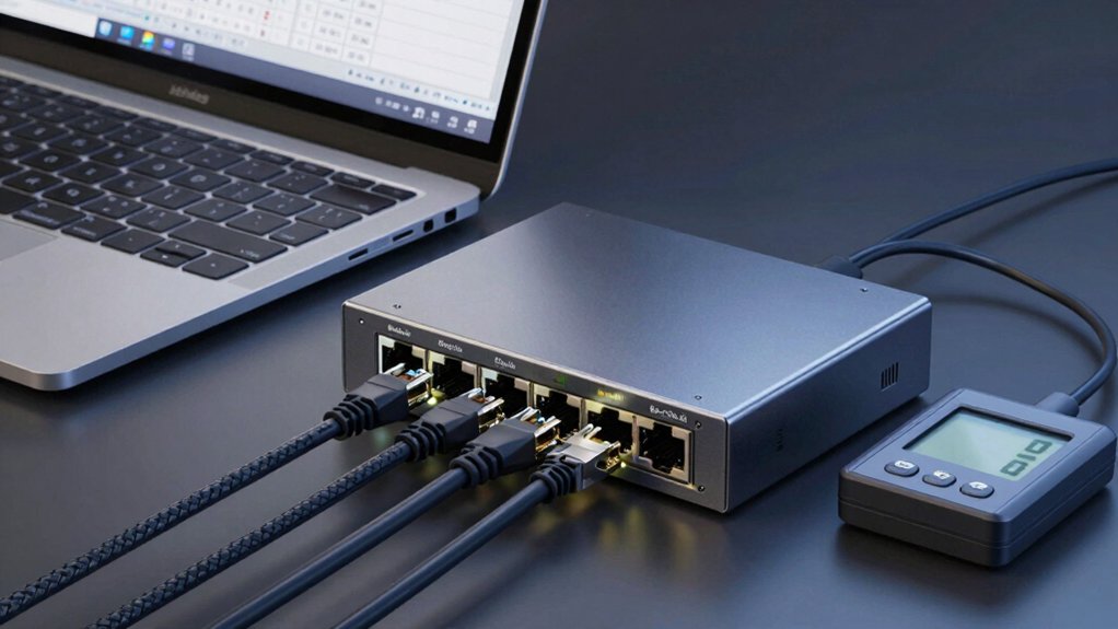
You’ll size PoE by listing every powered device’s datasheet wattage, summing those watts, and comparing the total with per‑port class limits to the switch’s PoE budget. Account for cable loss (≈10–25%), and apply environmental derates (benign ~0.7, harsh ~0.6, long‑term ~0.5) to derive an operational limit and headroom.
Reserve a spare port; plan injectors or midspans for overloads. Validate per‑port classifications; more implementation details follow.
Poe Switch Setup and Power Budgeting Basics: You’ll size PoE by listing every powered device’s datasheet wattage, summing those watts, and comparing the total with per‑port class limits to the switch’s PoE budget . Account for cable loss (≈10–25%), and apply environmental derates (benign ~0.7, harsh ~0.6, long‑term ~0.5) to derive an operational limit and headroom.
Quick Overview
- Confirm the switch’s total PoE budget (watts) and number of PoE-capable ports before planning device connections.
- Inventory each PD’s datasheet maximum wattage and assign a conservative per-port PD class (Class 1–4 / PoE/PoE+/PoE++).
- Sum per-port demands; include 10–25% uplift for cable/thermal losses, and compare to the switch budget.
- Apply environmental derating: benign 0.7, harsh 0.6, long-term 0.5 to get an operational PoE limit.
- Reserve spare ports and plan injectors/midspans or dedicated feeds for high-power devices to avoid overloads.
How to Calculate a PoE power budget (Quick Answer)
How do you quickly check that a switch can power all connected devices? First, confirm the switch’s total PoE budget in watts and the count of PoE-enabled ports. Then, note per-port power per supported standard (802.3af/at/bt).
Next, catalog each device’s maximum PD power from datasheets. Map Device classes to typical maxima: Class 0: 9–15.4 W; PoE/PoE+ and PoE++ ranges accordingly. Sum all device PD demands to get the required total PoE power budget and compare it to the switch’s total PoE budget.
Adjust the summed demand for environmental derating: apply 1/0.7, 1/0.6, or 1/0.5 as specified for benign, harsh, or conservative scenarios. Reserve at least one spare port for diagnostics and leave operational headroom above the adjusted total to prevent overrun.
If the adjusted demand exceeds the switch’s PoE budget, reduce loads, upgrade the switch, or distribute devices across additional PoE sources.
PoE Basics You Must Know (Voltage, Loss, and Device Classes)
Understand PoE fundamentals so you can correctly size and troubleshoot power delivery over Ethernet. PoE supplies both data and DC power over twisted-pair cable with nominal per-port source budgets of 15.4 W (Type 1), 30 W (Type 2), and up to 60–100 W for higher types. The powered device (PD) typically receives about 12.95 W for PoE and ~25.5 W for PoE+ after accounting for negotiation and cable losses.
You’ll identify PD class (1–4) to estimate real draw: Class 1/2 ~4–7 W, Class 3 ~15.4 W, Class 4 ~30 W. Cable length, gauge, and environment cause 10–25% loss from resistance and heat; design margins accordingly. Never mix PoE budgeting with an unrelated topic or irrelevant concept. Keep power calculations focused.
Sum PD maximums, include loss margin, then compare to switch total PoE budget. Use negotiation and polarity awareness to troubleshoot underpowered PDs.
| Item | Nominal W | Typical PD W |
|---|---|---|
| PoE | 15.4 W | 12.95 W |
| PoE+ | 30 W | 25.5 W |
| Margin | Loss 10–25% | Accounted |
How 802.3af / 802.3at / 802.3bt Change Per‑Port Power
Curious how the different 802.3 standards affect per‑port power? You need to know how PoE standards shift delivered watts so your power budgeting is accurate. Nominal ratings don’t equal PD delivery; expect cable loss and thermal loss to reduce delivered power by roughly 10–25%.
- 802.3af (PoE) supplies up to 15.4 W at the port. Typical PD delivery is ≈12.95 W after cable losses.
- 802.3at (PoE+) raises per‑port capacity to 30 W, supporting higher‑draw phones and cameras. Delivered watts depend on cable and temperature.
- 802.3bt Type 3 (PoE++) supports up to 60 W per port at the PSE. PDs typically see ≈51 W after losses.
- 802.3bt Type 4 is rated up to 100 W per port. Practical PD delivery commonly falls into the 51–71 W range depending on run length and heat.
Use per‑port classifications (Class 0–4) plus these delivered‑watt expectations when you perform power budgeting for switches and connected devices.
Step 1 : Inventory PoE Devices and Required Watts
Ready to start? You’ll inventory devices and perform a precise wattage calculation. List every PoE device and note its datasheet maximum wattage. Group by PoE class: Class 1–4, PoE, PoE+, or PoE++. Use PD maximums: 802.3af ≈15.4W (≈12.95W delivered), PoE+ up to 30W, and higher for PoE++. Round up and add a small margin per device to account for cable loss and transient peaks.
Keep one spare port for diagnostics or future expansion. Record results in a clear table and sum conservative per-port demands to form your demand figure; don’t yet size total switch power or headroom. This inventory devices step yields an accurate base for later provisioning. Maintain supporting documentation (datasheets and grouping) so wattage calculation is auditable and repeatable.
| Device | Max Watts (datasheet) |
|---|---|
| IP Camera A | 12.95W |
| AP B | 30W |
| Phone C | 15W |
| IoT Sensor D | 4W |
Step 2 : Total Switch Power, Port Reserves, and Headroom
How much usable PoE power do you really have once ports and headroom are accounted for? Start by confirming the switch’s total PoE budget (for example, 190W) and sum your PD watt requirements. PoE budgeting requires you to subtract reserved ports and maintain power headroom so the switch can handle spikes.
- Reserve one port for the router/internet uplink; that reduces available PoE ports and the practical budget for PDs.
- Verify per-port limits (Class 1 = 4W, Class 2 = 7W, Class 3 = 15.4W, Class 4 = 30W) and assign each device to its expected class.
- Compare the summed PD demand to the switch budget; keep aggregate demand well below 100% to preserve power headroom.
- If total demand approaches the budget, plan capacity increases or reclassify devices to maintain reliability and avoid overcommitment.
This step gives you a deterministic usable PoE power number for deployment decisions.
Step 3 : Adjust for Cable Loss, Environment, and Safety Margin
Want to be certain the power you plan on delivering actually reaches the device? Account for cable loss and temperature effects before finalizing budgets. Estimate 10–25% PD power reduction from cable loss based on length and conductor gauge; subtract that from per-port needs.
Then adjust for environment: benign sites typically operate around 70% of rated PoE budget due to temperature effects and other degradations. Harsher conditions demand larger derates. Use conservative margins: apply a 50% long-term efficiency margin (divide your Step 1 total by 0.5) to ensure safe delivery and longevity. For harsh locations with rugged PDs and supplies, consider recomputing using a 0.6 divisor instead of 0.7 where applicable.
Always reserve at least one spare port or additional headroom to accommodate unexpected devices or diagnostics. Document your assumptions (cable length, gauge, ambient temperature) so future changes can be recalculated without guesswork.
Choose the Right PoE Switch or Power Supply for Your Budget
Which switch or external supply will reliably deliver your calculated PoE budget? You’ll pick hardware by matching per-port limits and total switch budget to your summed PD demands from Step 2, accounting for device classes and reserved ports (e.g., one for the router).
- Check per-port type: Ensure ports support PoE (Type 1, 15.4W) or PoE+ (Type 2, 30W) to match device classes on each PD.
- Verify total budget: Choose a switch whose overall PoE budget exceeds your summed PD draw. For example, GS-7-2040-PV-2 has 190W for 24 ports.
- Select external PS when needed: Map your Step 2 budget ranges to compatible Comnet PS models (PS-DRA30-48A … PS-DRA480-48A) so the supply covers peak demand plus margin.
- Plan device class distribution: Count Class 1–4 devices to limit high-power ports and avoid overloading the switch. Always reserve ports for diagnostics and routing.
If the Switch Runs Out of PoE Budget: Injectors, Midspans, and Grouping
Running out of PoE budget? If your switch can’t meet total PD demand, don’t immediately replace it. Use PoE injectors to power individual devices that have separate data and power inputs. Each injector supplies local power while the switch handles data.
PoE midspans are another inline option; insert them between the switch and PDs to add PoE capability without changing the switch’s PSE budget. Group devices by power class and schedule or stagger high-demand PDs to prevent simultaneous draws that exceed the total budget. For high-power devices (PTZ, heaters, PoE++ gear), confirm the switch’s per-port class supports the device or feed those devices via injectors or midspans rated for the required wattage.
Always recalc total PD requirements after cable loss and environmental derating so grouping and additional injectors or midspans actually solve the deficit. This approach preserves existing infrastructure, targets upgrades efficiently, and maintains predictable power delivery to critical endpoints.
Pre‑Install Checklist to Validate Your PoE Deployment
Before you power and cable anything, verify the switch’s total PoE budget and map every PD to a port so you can confirm per-port class and aggregate draw. Then calculate the summed maximum device watts with a conservative uplift for cable loss. Reserve a spare port for diagnostics and flag any high-power PDs that will need injectors or dedicated feeds.
You’ll inventory ports, assign classes (4W, 7W, 15.4W, 30W), and compare the sum to the switch’s rated budget (e.g., 190W). Apply environment efficiency factors (benign 0.7, harsh 0.6, long-term 0.5) to derive an operational margin. Account for non-PoE devices and plan injectors or midspans for overload relief so critical PDs aren’t off topic during maintenance.
- Confirm total budget and per-port class.
- Sum device max watts with conservative uplift.
- Apply environmental efficiency to set operational limit.
- Reserve spare port and identify injector needs.
Avoid treating this as an unrelated topic; keep validation traceable and documented.
Frequently Asked Questions
Can I Mix Passive Poe and 802.3-Compliant Devices on One Switch?
Yes, but you shouldn’t. Mixing passive PoE and 802.3-compliant devices on one switch can work only if the switch explicitly supports both standards and isolates their ports. You’ll need to manage PoE power carefully and perform strict power budgeting per port so compliant devices aren’t damaged.
Passive loads don’t exhaust the budget. Verify port configuration, voltage compatibility, and per-port current limits before deploying mixed devices to avoid failures.
How Do Firmware Updates Affect Poe Power Allocation?
Firmware updates can change firmware implications for power allocation by altering negotiation, prioritization, and per-port limits. You’ll see revised PD classification, updated power-saving profiles, or different allocation algorithms that shift wattage per port or overall budget.
That can cause reboots, reduced available power, or improved efficiency. Always review release notes, test updates in a controlled environment, and adjust port priorities or budget reservations before deploying broadly.
Can Poe Switches Prioritize Critical Ports Automatically?
Yes, you can configure many PoE switches to automatically prioritize critical ports. You’ll set priority QoS rules and enable power budgeting features so the switch allocates available wattage to high-priority devices first.
The switch monitors consumption, enforces budget limits, and can preempt lower-priority ports when power is scarce. You’ll define port priority levels, thresholds, and failover behavior to ensure essential equipment keeps power during constrained conditions.
What Happens to Poe Power During Switch Redundancy/Failover?
During redundancy/failover, PoE power switches to the redundant power source and maintains connected devices if capacity allows. Failover behavior depends on switch design and power budget.
You’ll see instantaneous transfer with UPS-backed supplies or a brief interruption if sources switch. If the redundant supply lacks sufficient wattage, the switch will prioritize or shed ports per configured policies. This potentially disables lower-priority PDs to preserve power for critical devices.
Are There Special Grounding or Surge Protection Requirements for Poe?
Yes, you should follow grounding considerations and surge protection for PoE. You’ll bond switch chassis to building ground, use insulated grounding conductors, and maintain correct conductor sizes and terminations.
You’ll deploy surge protectors on AC mains and dedicated Ethernet surge devices or PD-side protection to clamp transients; these should be placed near switches or at demarcation points. You’ll follow vendor and local electrical codes to ensure predictable protection and avoid ground loops.
Conclusion
You’ve now got the method: Inventory every PoE device and its wattage. Tally total switch power and reserve per port. Then account for cable loss, temperature derating, and a safety margin.
Pick a switch or external supply that meets the adjusted budget; supplement with injectors/midspans or port grouping if needed. Validate power at the patch panel and endpoints before final install to avoid brownouts. Ensure reliable operation.
Related reading: 3af Vs 802 3at Vs 802 3bt Poe — a closer look at this topic.